|
Jungo WinDriver
Official Documentation
|
|
Jungo WinDriver
Official Documentation
|
This chapter explores the basic characteristics of the Universal Serial Bus (USB) and introduces WinDriver USB's features and architecture.
ℹ️ Note
The references to the WinDriver USB toolkit in this chapter relate to the standard WinDriver USB toolkit for development of USB host drivers.
USB (Universal Serial Bus) is an industry standard extension to the PC architecture for attaching peripherals to the computer. It was originally developed in 1995 by leading PC and telecommunication industry companies, such as Intel, Compaq, Microsoft and NEC. USB was developed to meet several needs, among them the needs for an inexpensive and widespread connectivity solution for peripherals in general and for computer telephony integration in particular, an easy-to-use and flexible method of reconfiguring the PC, and a solution for adding a large number of external peripherals. The USB standard meets these needs.
The USB specification allows for the connection of a maximum of 127 peripheral devices (including hubs) to the system, either on the same port or on different ports.
USB also supports Plug-and-Play installation and hot swapping.
The USB 1.1 standard supports both isochronous and asynchronous data transfers and has dual speed data transfer: 1.5 Mb/s (megabits per second) for low-speed USB devices and 12 Mb/s for full-speed USB devices (much faster than the original serial port). Cables connecting the device to the PC can be up to five meters (16.4 feet) long. USB includes built-in power distribution for low power devices and can provide limited power (up to 500 mA of current) to devices attached on the bus. The USB 2.0 standard supports a signalling rate of 480 Mb/s, known as **'high-speed'**, which is 40 times faster than the USB 1.1 full-speed transfer rate.
USB 2.0 is fully forward- and backward-compatible with USB 1.1 and uses existing cables and connectors. USB 2.0 supports connections with PC peripherals that provide expanded functionality and require wider bandwidth. In addition, it can handle a larger number of peripherals simultaneously. USB 2.0 enhances the user's experience of many applications, including interactive gaming, broadband Internet access, desktop and Web publishing, Internet services and conferencing.
The USB 3.2 Gen 1 standard supports a signalling rate of up to 5 Gb/s in a new mode known as SuperSpeed USB. The USB 3.2 Gen 2 standard supports a signalling rate of up to 10 Gb/s in a new mode known as SuperSpeed USB 10Gbps. The USB 3.2 Gen 2x2 standard supports a signalling rate of up to 20 Gb/s in newer modes also named SuperSpeed USB 20Gbps whilist preserving backwards compatibility with previous USB versions.
| New name | Old name | Original name | SuperSpeed name | Max name |
|---|---|---|---|---|
| USB 3.2 Gen 2x2 | N/A | USB 3.2 | SuperSpeed USB 20Gbps | 20Gbps |
| USB 3.2 Gen 2 | USB 3.1 Gen 2 | USB 3.1 | SuperSpeed USB 10Gbps | 10Gbps |
| USB 3.2 Gen 1 | USB 3.1 Gen 1 | USB 3.0 | SuperSpeed USB | 5Gbps |
Because of its benefits USB is currently enjoying broad market acceptance.
This section describes the main benefits of the USB standard and the WinDriver USB toolkit, which supports this standard:
The Universal Serial Bus (USB) consists of the following primary components:
USB Host
The USB host platform is where the USB host controller is installed and where the client software/device driver runs. The USB Host Controller is the interface between the hostand the USB peripherals. The host is responsible for detecting the insertion and removal of USB devices, managing the control and data flow between the host and the devices, providing power to attached devices and more.
USB Hub
A USB device that allows multiple USB devices to attach to a single USB port ona USB host. Hubs on the back plane of the hosts are called root hubs. Other hubs are called external hubs.
USB Function
A USB device that can transmit or receive data or control information over the bus and that provides a function. A function is typically implemented as a separate peripheral device that plugs into a port on a hub using a cable. However, it is also possible to create a compound device, which is a physical package that implements multiple functions and anembedded hub with a single USB cable. A compound device appears to the host as a hub with one or more non-removable USB devices, which may have ports to support the connection of external devices.
During the operation of a USB device, the host can initiate a flow of data between the client software and the device.
Data can be transferred between the host and only one device at a time (peer to peer communication). However, two hosts cannot communicate directly, nor can two USB devices (with the exception of On-The-Go (OTG) devices, where one device acts as the master (host) and the other as the slave.)
The data on the USB bus is transferred via pipes that run between software memory buffers on the host and endpoints on the device.
Data flow on the USB bus is half-duplex, i.e., data can be transmitted only in one direction at a given time.
An endpoint is a uniquely identifiable entity on a USB device, which is the source or terminus ofthe data that flows from or to the device. Each USB device, logical or physical, has a collection of independent endpoints. The three USB speeds (low, full and high) all support one bi-directional control endpoint (endpoint zero) and 15 unidirectional endpoints. Each unidirectional endpoint can be used for either inbound or outbound transfers, so theoretically there are 30 supportedend points. Each endpoint has the following attributes: bus access frequency, bandwidth requirement, endpoint number, error handling mechanism, maximum packet size that can be transmitted or received, transfer type and direction (into or out of the device).
USB Endpoints
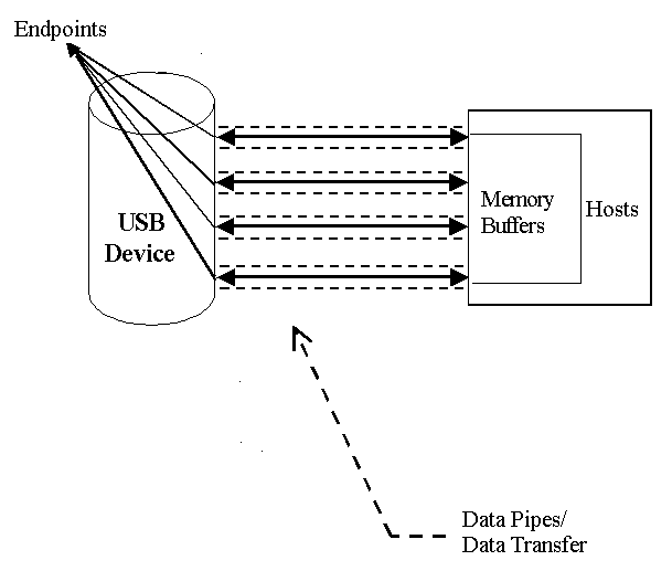
A pipe is a logical component that represents an association between an endpoint on the USB device and software on the host. Data is moved to and from a device through a pipe. A pipe can be either a stream pipe or a message pipe, depending on the type of data transfer used in the pipe. Stream pipes handle interrupt, bulk and isochronous transfers, while message pipes support the control transfer type.
The USB standard supports two kinds of data exchange between a host and a device: functional data exchange and control exchange.
Functional Data Exchange is used to move data to and from the device. There are three types of USB data transfers: Bulk, Interrupt and Isochronous.
Control Exchange is used to determine device identification and configuration requirements, and to configure a device; it can also be used for other device-specific purposes, including control of other pipes on the device. Control exchange takes place via a control pipe — the default pipe 0, which always exists. The control transfer consists of a setup stage (in which a setup packet is sent from the host to the device), an optional data stage and a status stage.
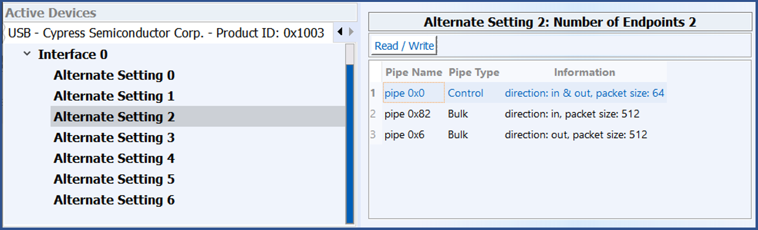
The figure below depicts a USB device with one bi-directional control pipe (endpoint) and two functional data transfer pipes (endpoints), as identified by WinDriver's DriverWizard utility.
USB Pipes
The USB device (function) communicates with the host by transferring data through a pipe between a memory buffer on the host and an endpoint on the device. USB supports four different transfer types. A type is selected for a specific endpoint according to the requirements of the device and the software. The transfer type of a specific endpoint is determined in the endpoint descriptor.
The USB specification provides for the following data transfer types:
Control Transfer is mainly intended to support configuration, command and status operations between the software on the host and the device.
This transfer type is used for low-, full- and high-speed devices.
Each USB device has at least one control pipe (default pipe), which provides access to the configuration, status and control information.
Control transfer is bursty, non-periodic communication.
The control pipe is bi-directional — i.e., data can flow in both directions.
Control transfer has a robust error detection, recovery and retransmission mechanism and retries are made without the involvement of the driver.
The maximum packet size for control endpoints can be only 8 bytes for low-speed devices; 8, 16,32, or 64 bytes for full-speed devices; and only 64 bytes for high-speed devices.
For more in-depth information regarding USB control transfers and their implementation,
refer to Chapter 14: USB Advanced Features of the manual.
Isochronous Transfer is most commonly used for time-dependent information, such as multimedia streams and telephony.
This transfer type can be used by full-speed and high-speed devices, but not by low-speed devices.
Isochronous transfer is periodic and continuous.
The isochronous pipe is unidirectional, i.e., a certain endpoint can either transmit or receive information. Bi-directional isochronous communication requires two isochronous pipes, one in each direction.
USB guarantees the isochronous transfer access to the USB bandwidth (i.e., it reserves the required amount of bytes of the USB frame) with bounded latency, and guarantees the data transfer rate through the pipe, unless there is less data transmitted.
Since timeliness is more important than correctness in this type of transfer, no retries are made in case of error in the data transfer. However, the data receiver can determine that an error occurred on the bus.
Interrupt Transfer is intended for devices that send and receive small amounts of data infrequently or in an asynchronous time frame.
This transfer type can be used for low-, full- and high-speed devices.
Interrupt transfer type guarantees a maximum service period and that delivery will be re-attempted in the next period if there is an error on the bus.
The interrupt pipe, like the isochronous pipe, is unidirectional and periodical.
The maximum packet size for interrupt endpoints can be 8 bytes or less for low-speed devices; 64bytes or less for full-speed devices; and 1,024 bytes or less for high-speed devices.
Bulk Transfer is typically used for devices that transfer large amounts of non-time sensitive data, and that can use any available bandwidth, such as printers and scanners.
This transfer type can be used by full-speed and high-speed devices, but not by low-speed devices.
Bulk transfer is non-periodic, large packet, bursty communication.
Bulk transfer allows access to the bus on an "as-available" basis, guarantees the data transfer but not the latency, and provides an error check mechanism with retries attempts. If part of the USB bandwidth is not being used for other transfers, the system will use it for bulk transfer.
Like the other stream pipes (isochronous and interrupt), the bulk pipe is also unidirectional, so bi-directional transfers require two endpoints.
The maximum packet size for bulk endpoints can be 8, 16, 32, or 64 bytes for full-speed devices, and 512 bytes for high-speed devices.
Before the USB function (or functions, in a compound device) can be operated, the devicemust be configured. The host does the configuring by acquiring the configuration information from the USB device. USB devices report their attributes by descriptors. A descriptor is the defined structure and format in which the data is transferred. A complete description of the USB descriptors can be found in 14.2. USB Control Transfers Overview.
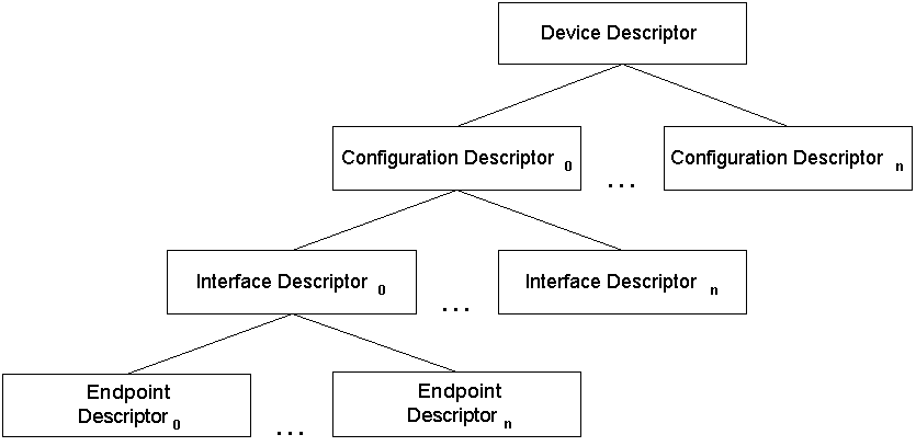
It is best to view the USB descriptors as a hierarchical structure with four levels:
There is only one device descriptor for each USB device. Each device has one or more configurations, each configuration has one or more interfaces, and each interface has zero or more endpoints.
Device Descriptors
Device Level
The device descriptor includes general information about the USB device, i.e. global information for all of the device configurations. The device descriptor identifies, among other things, the device class (HID device, hub, locator device, etc.), subclass, protocol code,vendor ID, device ID and more. Each USB device has one device descriptor.
Configuration Level
A USB device has one or more configuration descriptors. Each descriptor identifies the number of interfaces grouped in the configuration and the power attributes of the configuration (such as self-powered, remote wakeup, maximum power consumption and more). Only one configuration can be loaded at a given time. For example, an ISDN adapter might have two different configurations, one that presents it with a single interface of 128 Kb/s and a second that presents it with two interfaces of 64 Kb/s each.
Interface Level
The interface is a related set of endpoints that present a specific functionality or feature of the device. Each interface may operate independently. The interface descriptor describes the number of the interface, the number of endpoints used by this interface and the interface-specific class, subclass and protocol values when the interface operates independently.
In addition, an interface may have alternate settings. The alternate settings allow the endpoints or their characteristics to be varied after the device is configured.
Endpoint Level
The lowest level is the endpoint descriptor, which provides the host with information regarding the endpoint's data transfer type and maximum packet size. For isochronous endpoints, the maximum packet size is used to reserve the required bus time forthe data transfer — i.e., the bandwidth. Other endpoint attributes are its bus access frequency, endpoint number, error handling mechanism and direction. The same endpoint can have different properties (and consequently different uses) in different alternate settings.
Seems complicated? Not at all! WinDriver automates the USB configuration process. The included DriverWizard utility and USB diagnostics application scan the USB bus, detect all USB devices and their configurations, interfaces, alternate settings and endpoints, and enable you to pick the desired configuration before starting driver development.
WinDriver identifies the endpoint transfer type as determined in the endpoint descriptor. The driver created with WinDriver contains all configuration information acquired at this early stage.
WinDriver USB enables developers to quickly develop high-performance drivers for USB-based devices without having to learn the USB specifications and operating system internals, or use the operating system development kits. For example, Windows drivers can be developed without using the Windows Driver Kit (WDK) or learning the Windows Driver Model (WDM).
The driver code developed with WinDriver USB is binary compatible across the supported Windows platforms and source code compatible across all supported operating systems. For an up-to-date list of supported operating systems, see 1.4. Supported Platforms.
WinDriver USB is a generic tool kit that supports all USB devices from all vendors and with all types of configurations.
WinDriver USB encapsulates the USB specification and architecture, letting you focus on your application logic. WinDriver USB features the graphical DriverWizard utility, which enables you to easily detect your hardware, view its configuration information, and test it, before writing a single line of code: DriverWizard first lets you choose the desired configuration, interface and alternate setting combination, using a friendly graphical user interface. After detecting and configuring your USB device, you can proceed to test the communication with the device — perform data transfers on the pipes, send control requests, reset the pipes, etc. — in order to ensure that all your hardware resources function as expected.
After your hardware is diagnosed, you can use DriverWizard to automatically generate your device driver source code. WinDriver USB provides user-mode APIs, which you can call from within your application in order to implement the communication with your device. The WinDriver USB API includes USB-unique operations such as reset of a pipe or a device. The generated DriverWizard code implements a diagnostics application, which demonstrates how to use WinDriver's USB API to drive your specific device. In order to use the application you just need to compile and run it. You can jump-start your development cycle by using this application as your skeletal driver and then modifying the code as needed to implement the desired driver functionality for your specific device.
DriverWizard also automates the creation of an INF file that registers your device to work with WinDriver, which is an essential step in order to correctly identify and handle USB devices using WinDriver.
With WinDriver USB, all development is done in the user mode, using familiar development and debugging tools and your favorite compiler or development environment (such as MS Visual Studio, CMake, GCC, Windows GCC).
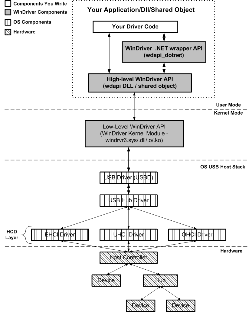
To access your hardware, your application calls the WinDriver kernel module using functions from the WinDriver USB API. The high-level functions utilize the low-level functions, which use IOCTLs to enable communication between the WinDriver kernel module and your user-mode application. The WinDriver kernel module accesses your USB device resources through the native operating system calls.
There are two layers responsible for abstracting the USB device to the USB device driver. The upper layer is the USB Driver (USBD) layer, which includes the USB Hub Driver and the USB Core Driver. The lower level is the Host Controller Driver (HCD) layer. The division of duties between the HCD and USBD layers is not defined and is operating system dependent. Both the HCD and USBD are software interfaces and components of the operating system, where the HCD layer represents a lower level of abstraction.
The HCD is the software layer that provides an abstraction of the host controller hardware, while the USBD provides an abstraction of the USB device and the data transfer between the host software and the function of the USB device.
The USBD communicates with its clients (the specific device driver, for example) through the USB Driver Interface (USBDI). At the lower level, the Core Driver and USB Hub Driver implement the hardware access and data transfer by communicating with the HCD using the Host Controller Driver Interface (HCDI).
The USB Hub Driver is responsible for identifying the addition and removal of devices from a particular hub. When the Hub Driver receives a signal that a device was attached or detached, it uses additional host software and the USB Core Driver to recognize and configure the device. The software implementing the configuration can include the hub driver, the device driver, and other software.
WinDriver USB abstracts the configuration procedure and hardware access described above for the developer. With WinDriver's USB API, developers can perform all the hardware-related operations without having to master the lower-level implementation for supporting these operations.
WinDriver USB Architecture
This section provides a general overview of WinDriver's USB Library (WDU), including:
The WDU library's interface is found in the WinDriver/include/wdu_lib.h and
WinDriver/include/windrvr.h header files, which should be included from any source file that calls the WDU API (wdu_lib.h already includes windrvr.h).
The WinDriver WDU_xxx USB API is designed to support event-driven transfers between your user-mode USB application and USB devices. This is in contrast to earlier versions, in which USB devices were initialized and controlled using a specific sequence of function calls.
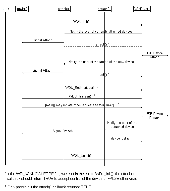
You can implement the three user callback functions specified in the next section: WDU_ATTACH_CALLBACK, WDU_DETACH_CALLBACK and WDU_POWER_CHANGE_CALLBACK (at the very least WDU_ATTACH_CALLBACK). These functions are used to notify your application when a relevant system event occurs, such as the attaching or detaching of a USB device. For best performance, minimal processing should be done in these functions.
Your application calls WDU_Init() and provides the criteria according to which the system identifies a device as relevant or irrelevant. The WDU_Init() function must also pass pointers to the user callback functions.
Your application then simply waits to receive a notification of an event. Upon receipt of such a notification, processing continues. Your application may make use of any functions defined in the high- or low-level APIs below. The high-level functions, provided for your convenience, make use of the low-level functions, which in turn use IOCTLs to enable communication between the WinDriver kernel module and your user-mode application.
When exiting, your application calls WDU_Uninit() to stop listening to devices matching the given criteria and to unregister the notification callbacks for these devices.
The following figure depicts the calling sequence described above. Each vertical line represents a function or process. Each horizontal arrow represents a signal or request, drawn from the initiator to the recipient. Time progresses from top to bottom.
WinDriver USB Calling Sequence
The following piece of meta-code can serve as a framework for your user-mode application's code:
The WinDriver WDU_xxx USB API, provided beginning with version 6.0.0, is designed to support event-driven transfers between your user-mode USB application and USB devices. This is in contrast to earlier versions, in which USB devices were initialized and controlled using a specific sequence of function calls.
As a result of this change, you will need to modify your USB applications that were designed to interface with earlier versions of WinDriver to ensure that they will work with WinDriver versions 6.X on all supported platforms and not only on Microsoft Windows.
You will have to reorganize your application's code so that it conforms with the framework illustrated by the piece of meta-code provided in 5.10.1. Calling Sequence for WinDriver USB
In addition, the functions that collectively define the USB API have been changed. The new functions provide an improved interface between user-mode USB applications and the WinDriver kernel module. Note that the new functions receive their parameters directly, unlike the old functions, which received their parameters using a structure.
The table below lists the legacy functions in the left column and indicates in the right column which function or functions replace(s) each of the legacy functions. Use this table to quickly determine which new functions to use in your new code.
| Low Level API | High Level API |
|---|---|
| Previous Function | New Function |
| WD_Open(), WD_Version(), WD_UsbScanDevice() | WDU_Init() |
| WD_UsbDeviceRegister() | WDU_SetInterface() |
| WD_UsbGetConfiguration() | WDU_GetDeviceInfo() |
| WD_UsbDeviceUnregister() | WDU_Uninit() |
| WD_UsbTransfer() | WDU_Transfer(), WDU_TransferDefaultPipe(), WDU_TransferBulk(), WDU_TransferIsoch(), WDU_TransferInterrupt() |
| USB_TRANSFER_HALT option | WDU_HaltTransfer() |
| WD_UsbResetPipe() | WDU_ResetPipe() |
| WD_UsbResetDevice(), WD_UsbResetDeviceEx() | WDU_ResetDevice() |
You can use WDU_ResetDevice().