|
Jungo WinDriver
Official Documentation
|
|
Jungo WinDriver
Official Documentation
|
The USB standard supports two kinds of data exchange between the host and the device — control exchange and functional data exchange. The WinDriver APIs enable you to implement both control and functional data transfers.
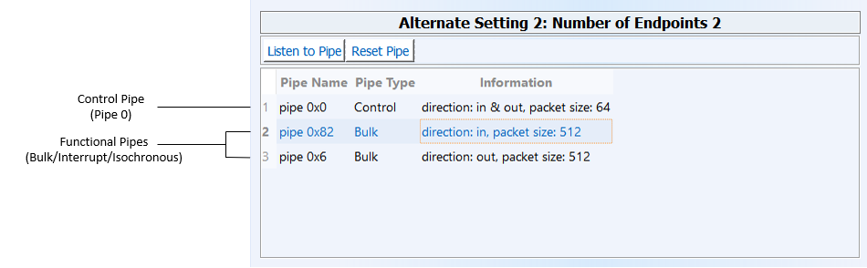
The figure below demonstrates how a device's pipes are displayed in the DriverWizard utility, which enables you to perform transfers from a GUI environment.
USB Data Exchange
USB control exchange is used to determine device identification and configuration requirements, and to configure a device; it can also be used for other device-specific purposes, including control of other pipes on the device.
Control exchange takes place via a control pipe — the default pipe 0, which always exists. The control transfer consists of a setup stage (in which a setup packet is sent from the host to the device), an optional data stage and a status stage.
The control transaction always begins with a setup stage. The setup stage is followed by zero or more control data transactions (data stage) that carry the specific information for the requested operation, and finally a status transaction completes the control transfer by returning the status to the host.
During the setup stage, an 8-byte setup packet is used to transmit information to the control endpoint of the device (endpoint 0). The setup packet's format is defined by the USB specification.
A control transfer can be a read transaction or a write transaction. In a read transaction the setup packet indicates the characteristics and amount of data to be read from the device. In a write transaction the setup packet contains the command sent (written) to the device and the number of control data bytes that will be sent to the device in the data stage.
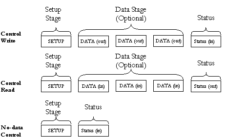
Refer to the figure provided below (and taken from the USB specification) for a sequence of read and write transactions:
⚠ Attention
'(in)' indicates data flow from the device to the host. '(out)' indicates data flow from the host to the device.
USB Read and Write
The setup packets (combined with the control data stage and the status stage) are used to configure and send commands to the device. USB requests such as these are sent from the host to the device, using setup packets. The USB device is required to respond properly to these requests. In addition, each vendor may define device-specific setup packets to perform device-specific operations. The standard setup packets (standard USB device requests) are detailed below. The vendor's device-specific setup packets are detailed in the vendor's data book for each USB device.
The table below shows the format of the USB setup packet. For more information, please refer to the USB specification at http://www.usb.org.
| Byte | Field | Description |
|---|---|---|
| 0 | bmRequest Type | Bit 7: Request direction (0=Host to device — Out, 1=Device to host— In). Bits 5-6: Request type (0=standard, 1=class, 2=vendor, 3=reserved). Bits 0-4: Recipient (0=device, 1=interface, 2=endpoint,3=other). |
| 1 | bRequest | The actual request (see the Standard Device Request Codes table below) |
| 2 | wValueL | A word-size value that varies according to the request. For example,in the CLEAR_FEATURE request the value is used to select the feature. In the GET_DESCRIPTOR request the value indicatesthe descriptor type and in the SET_ADDRESS request the value contains the device address. |
| 3 | wValueH | The upper byte of the Value word. |
| 4 | wIndexL | A word-size value that varies according to the request. The index is generally used to specify an endpoint or an interface. |
| 5 | wIndexH | The upper byte of the Index word. |
| 6 | wLengthL | A word-size value that indicates the number of bytes to be transferred if there is a data stage. |
| 7 | wLengthH | The upper byte of the Length word. |
The table below shows the standard device request codes.
| bRequest | Value |
|---|---|
| GET_STATUS | 0 |
| CLEAR_FEATURE | 1 |
| Reserved for future use | 2 |
| SET_FEATURE | 3 |
| Reserved for future use | 4 |
| SET_ADDRESS | 5 |
| GET_DESCRIPTOR | 6 |
| SET_DESCRIPTOR | 7 |
| GET_CONFIGURATION | 8 |
| SET_CONFIGURATION | 9 |
| GET_INTERFACE | 10 |
| SET_INTERFACE | 11 |
| SYNCH_FRAME | 12 |
This example of a standard USB device request illustrates the setup packet format and its fields. The setup packet is in Hex format.
The following setup packet is for a control read transaction that retrieves the device descriptor from the USB device. The device descriptor includes information such as USB standard revision, vendor ID and product ID.
| GET_DESCRIPTOR (Device) Setup Packet | |||||||
|---|---|---|---|---|---|---|---|
| 80 | 06 | 00 | 01 | 00 | 00 | 12 | 00 |
Setup packet meaning:
| Byte | Field | Value | Description |
|---|---|---|---|
| 0 | bmRequest Type | 80 | 8h=1000b bit 7=1 -> direction of data is from device to host. 0h=0000b bits 0..1=00 -> the recipient is the device. |
| 1 | bRequest | 06 | The Request is GET_DESCRIPTOR. |
| 2 | wValueL | 00 | |
| 3 | wValueH | 01 | The descriptor type is device (values defined in USB spec). |
| 4 | wIndexL | 00 | The index is not relevant in this setup packet since there is only one device descriptor. |
| 5 | wIndexH | 00 | |
| 6 | wLengthL | 12 | Length of the data to be retrieved: 18(12h) bytes (this is the length of the device descriptor). |
| 7 | wLengthH | 00 |
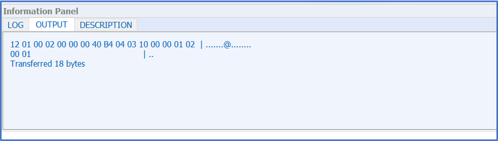
In response, the device sends the device descriptor data. A device descriptor of the Cypress EZ-USB Integrated Circuit is provided as an example:
| Byte No. | Content |
|---|---|
| 0 | 0x12 |
| 1 | 0x01 |
| 2 | 0x00 |
| 3 | 0x01 |
| 4 | 0xff |
| 5 | 0xff |
| 6 | 0xff |
| 7 | 0x40 |
| 8 | 0x47 |
| 9 | 0x05 |
| 10 | 0x80 |
| 11 | 0x00 |
| 12 | 0x01 |
| 13 | 0x00 |
| 14 | 0x00 |
| 15 | 0x00 |
| 16 | 0x00 |
| 17 | 0x01 |
As defined in the USB specification, byte 0 indicates the length of the descriptor, bytes 2-3 contain the USB specification release number, byte 7 is the maximum packet size for the control endpoint (endpoint 0), bytes 8-9 are the vendor ID, bytes 10-11 are the product ID, etc.
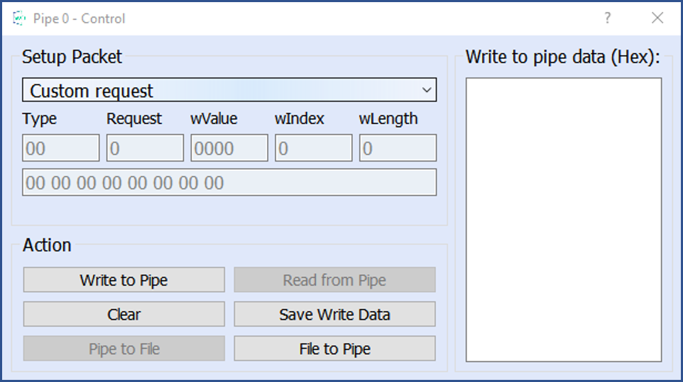
WinDriver allows you to easily send and receive control transfers on the control pipe (pipe0), while using DriverWizard to test your device. You can either use the API generated by DriverWizard for your hardware, or directly call the WinDriver WDU_Transfer() function from within your application.
For a custom request: enter the required setup packet fields. For a write transaction that includes a data stage, enter the data in the Write to pipe data (Hex) field. Click Read From Pipe or Write To Pipe according to the required transaction.
Custom Request
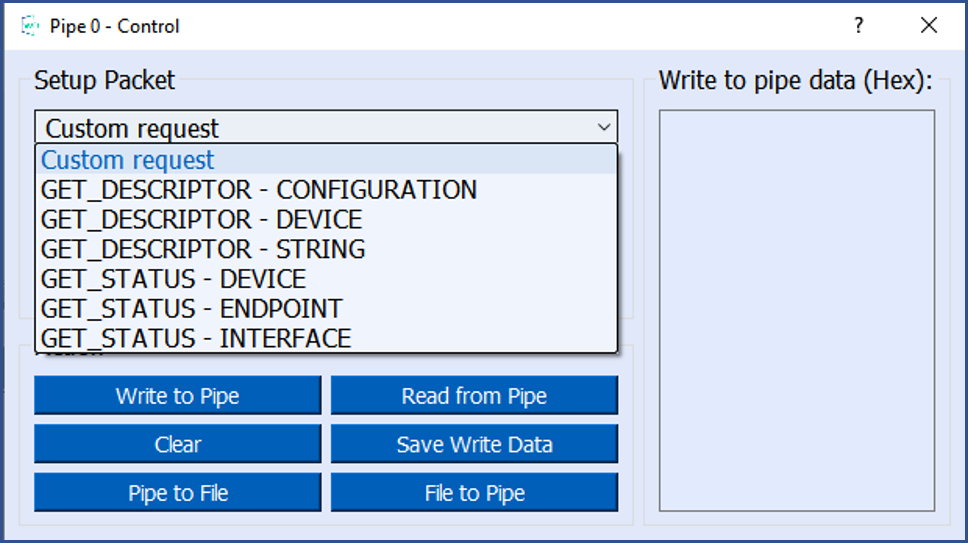
For a standard USB request: select a USB request from the requests list, which includes requests such as GET_DESCRIPTOR CONFIGURATION, GET_DESCRIPTOR DEVICE, GET_STATUS DEVICE, etc. The description of the selected request will be displayed in the Request Description box on the right hand of the dialogue window.
Request List
USB Request Log
To perform a read or write transaction on the control pipe, you can either use the API generated by DriverWizard for your hardware, or directly call the WinDriver [WDU_Transfer] (WDU_Transfer) function from within your application. Fill the setup packet in the BYTE SetupPacket[8] array and call these functions to send setup packets on the control pipe (pipe 0) and to retrieve control and status data from the device.
The following sample demonstrates how to fill the SetupPacket[8] variable with a GET_DESCRIPTOR setup packet:
The following sample demonstrates how to send a setup packet to the control pipe (a GET instruction; the device will return the information requested in the pBuffer variable):
The following sample demonstrates how to send a setup packet to the control pipe (a SET instruction):
Refer for further information to WDU_Transfer().
Functional USB data exchange is used to move data to and from the device. There are three types of USB data transfers: Bulk, Interrupt and Isochronous. Functional USB data transfers can be implemented using two alternative methods: single-blocking transfers and streaming transfers, both supported by WinDriver, as explained in the following sections. The generated DriverWizard USB code and the generic WinDriver/util/usb_diag.exe utility (source code located under the WinDriver/samples/c/usb_diag directory) enable the user to select which type of transfer to perform.
WinDriver's WDU_Transfer() function, and the WDU_TransferBulk(), WDU_TransferIsoch(),
and WDU_TransferInterrupt() convenience functions enable you to easily impelment single-blocking USB data transfers. You can also perform single-blocking transfers using the DriverWizard utility (which uses the WDU_Transfer() function).
In the streaming USB data transfer scheme, data is continuously streamed between the host and the device, using internal buffers allocated by the host driver — "streams".
Stream transfers allow for a sequential data flow between the host and the device, and can be used to reduce single-blocking transfer overhead, which may occur as a result of multiple function calls and context switches between user and kernel modes. This is especially relevant for devices with small data buffers, which might, for example, overwrite data before the host is able to read it, due to a gap in the data flow between the host and device.
WinDriver's WDU_StreamOpen() / WDU_StreamClose() / WDU_StreamStart() / WDU_StreamStop() / WDU_StreamFlush() / WDU_StreamRead() / WDU_StreamWrite() / WDU_StreamGetStatus() functions enable you to impelment USB streaming data transfers.
⚠ Attention
These functions are currently supported on Windows.
To begin performing stream transfers, call the WDU_StreamOpen() function. When this function is called, WinDriver creates a new stream object for the specified data pipe. You can open a stream for any pipe except for the control pipe (pipe 0). The stream's data transfer direction— read/write — is derived from the direction of its pipe.
WinDriver supports both blocking and non-blocking stream transfers. The open function's fBlocking parameter indicates which type of transfer to perform (see explanation below). Streams that perform blocking transfers will henceforth be referred to as "blocking streams", and streams that perform non-blocking transfers will be referred to as "non-blocking streams". The function's dwRxTxTimeout parameter indicates the desired timeout period for transfers between the stream and the device.
After opening a stream, call WDU_StreamStart() to begin data transfers between the stream's data buffer and the device.
In the case of a read stream, the driver will constantly read data from the device into the stream's buffer, in blocks of a pre-defined size (as set in the dwRxSize parameter of the WDU_StreamOpen() function. In the case of a write stream, the driver will constantl ycheck for data in the stream's data buffer and write any data that is found to the device.
To read data from a read stream to the user-mode host application, call WDU_StreamRead().
In case of a blocking stream, the read function blocks until the entire amount of data requested by the application is transferred from the stream to the application, or until the stream's attempt to read data from the device times out. In the case of a non-blocking stream, the function transfers to the application as much of the requested data as possible, subject to the amount of data currently available in the stream's data buffer, and returns immediately.
To write data from the user-mode host application to a write the stream, call WDU_StreamWrite().
In case of a blocking stream, the function blocks until the entire data is written to the stream, or until the stream's attempt to write data to the device times out. In the case of a non-blocking stream, the function writes as much of the write data as currently possible to the stream, and returns immediately.
For both blocking and non-blocking transfers, the read/write function returns the amount of bytes actually transferred between the stream and the calling application within an output parameter —pdwBytesRead/pdwBytesWritten.
You can flush an active stream at any time by calling the WDU_StreamFlush() function, which writes the entire contents of the stream's data buffer to the device (for a write stream), and blocks until all pending I/O for the stream is handled. You can flush both blocking and non-blocking streams.
You can call WDU_StreamGetStatus() for any open stream in order to get the stream's current status information.
To stop the data streaming between an active stream and the device, call WDU_StreamStop(). In the case of a write stream, the function flushes the stream — i.e., writes its contents to the device — before stopping it. An open stream can be stopped and restarted at any time until it is closed.
To close an open stream, call WDU_StreamClose(). The function stops the stream, including flushing its data to the device (in the case of a write stream), before closing it.
⚠ Attention
Each call to WDU_StreamOpen() must have a matching call to WDU_StreamClose() later on in the code in order to perform the necessary cleanup.
The 0xC000000C error code, is defined in windrvr.h as WD_USBD_STATUS_BUFFER_OVERRUN.
The WD_USBD_XXX status codes returned by WinDriver (see windrvr.h) comply with the URB status codes returned by the low-level USB stack driver (e.g., URB code 0XC000000CL — WD_USBD_STATUS_BUFFER_OVERRUN). You can refer to the Debug Monitor log to see the URB and IRP values returned from the stack drivers.
For Windows, the URB and IRP codes can be found in the Windows Driver Kit (WDK) under the inc\ directory. The URB status codes can be found in the usbdi.h file or the usb.h file (depending on the OS). The IRP status codes can be found in the ntstatus.h file. For Linux, WinDriver translates the error codes returned from the stack driver into equivalent USBD errors.
For information regarding the specific error you received and when it might occur, review the operating system’s documentation.
The USBD_STATUS_BUFFER_OVERRUN error code (0xC000000C) is set by the USB stack drivers when the device transfers more data than requested by the host.
There are two possible solutions for this buffer overrun problem:
💡 Recommendation
Recheck your firmware and the hardware specification to verify that you are implementing the communication with the device correctly. It is also recommended to use a USB bus analyzer to determine what is happening on the bus.
You can use WinDriver’s WDU_GetStringDesc() function to get the desired string descriptors.
Use WDU_Init() to register to listen for the notifications you are interested in.
You should set the pBuffer parameter of the WDU_Transfer() function to NULL and set the dwBufferSize parameter to 0.
No. Windriver USB is designed for writing drivers for USB devices (USB client drivers). It cannot be used to write a USB hub or a USB Host Controller driver.
Yes. WinDriver provides WDU_Stream functions for peforming streaming USB data transfers on Windows.